
Fri (March)
Today we are going to be learning how to flash an LED on a microcontroller by writing ARM assembly.
If you write software but are unfamiliar with basic electronics or embedded software development, there will be explanations of some fundamentals – I expect you will not feel left behind:).
If you’d like to skip the fundamentals and go straight to the assembly writing, click here .
We’ll be using a 1bitsy , which is an STM development board. We’ll be reading the STM (reference manual to figure out what assembly to write. If you want to try out the coding yourself, but don’t have a 1bitsy or anything similar, check out this Github repo where you can run the code on an emulator in a Docker container.
Let’s get some basics out of the way. How do you flash an LED?
Hardware
As you may know, an LED is a “light-emitting diode”. LEDs are It is popular in torches, bulbs and various other lighting due to their ability to be very bright with relatively low power. What we need to know is that they emit light when current passes through them. So: we need some current.
 This is just a simple electronics circuit with current flowing through the LED. We have low voltage at the bottom, and higher voltage at the top: that difference causes current to flow, lighting up our LED. But this is no good for us – we want to control the flow of current so that we can flash our LED on and off.
In order to control the current in our LED, we can connect it to a GPIO pin on our microcontroller:
GPIO just stands for “general purpose input / output”. It’s a pin on a microchip that you can configure at runtime: for example, you can say “I want this pin to be an output, and I want to turn it on “, or” I want this pin to be an input “and then read data from it.
A microcontroller is a small computer used for embedded software – we’ll learn more about the specific micrcontroller we’re using later. Embedded software is software that isn’t written for a general purpose computer, but instead targets specific hardware used in some physical device: for example, the software that Runs on an MRI scanner to control its operation, or the software in modern cars that controls things like the anti-lock braking system.
Software
If GPIO pins are configurable at runtime, then we need to write some code that will tell our little computer how to configure the GPIO. This is how that would usually look:
Usually, you’d expect that code to be written in C. You need a language that allows you control over memory the way that C does: when you have small limited memory, as is generally the case on small embedded computers, It’s important to be able to understand how much memory is being used by your program. Languages that rely on dynamic allocation and garbage collection are a bad fit, partly for this reason.
 Rust and C are also used for embedded work. The C you’d write for embedded would be quite different from what you might write for a desktop application – you likely wouldn’t use any of the STL containers as they all rely on dynamic memory allocation. Eliminating dynamic memory allocation is safer: the risk of memory allocation failing is much higher when there isn’t much memory to begin with. And a failure could be much more catastrophic: many embedded Systems are designed to run autonomously, without any human there to restart them. Many control safety-critical physical systems.
Dynamic allocation is generally not needed anyway: a desktop application might have to dynamically allocate resources to accommodate a user opening an unknown number of tabs in a GUI; an embedded application will know at compile time how many motors it has to control, or how many sensors it will read from. This allows a lot of memory to be allocated statically.
So, for the sake of example let’s say that you would write your code to flash an LED in C. You’d probably use a hardware abstraction library (aka a HAL) to abstract over memory addresses and such. This makes the code more portable as well as more readable.
But today, we’re going to do stuff a little differently from how you might Normally: we’ll be writing all our code in assembly.
What is assembly?
When you compile a C program, say, you compile it to machine code. Machine code is the lowest level of software – it’s the binary code that the CPU executes. This machine code consists of instructions . For example, you might have one instruction that says “copy value 46 into register 0 “, and that is our smallest unit of executable code.
Assembly is the next level of software up – it’s a lot like writing human readable machine code, where you write out each instruction in text form. This is very different to writing a C program which is much further abstracted, which means compiling C to machine code is a lot more complicated. When we write assembly today, that’s exactly what our CPU is going to be executing: There is a very close mapping to the actual machine code.
Why write our code in assembly?
The usual reasons: for fun and learning! Writing code in assembly means really getting to know your target hardware. Plus, we’ll know exactly what code is running on our processor.
Although this isn’t something you might usually do, understanding assembly code is a big part of many developers’ jobs: reading the assembly is often the only way to debug optimized code, and it’s crucial to reverse engineering and exploit development. It’s also key to compiler development, and used for making specific optimizations to embedded code. It’s often the only way to access Specialized CPU features, and to run special instructions like DSP instructions.
Doing embedded development means really getting to know your target hardware. So, what hardware are we using?
We have an ARM development board called a 1bitsy. It has an STM F4 on it, which is our microcontroller unit, or MCU. This microcontroller is basically the CPU plus about a megabyte of flash and 0553 kilobytes of RAM, and what are called peripherals: some of these are for communicating via various protocols, and some are for general purposes usage, like the GPIOs we talked about earlier. The MCU has everything you need to make the CPU actually be a useful computer. Our STM contains a Cortex M4 CPU – the picture above is of the die of the STM 39, it’s basically what’s inside the black plastic on the outside of the chip. The CPU is on the top right of the die, With RAM top left, flash bottom left, and peripherals bottom right.
I’ve included lists of the documentation associated with these. Today we’re exclusively going to be looking at the schematic for the board and the reference manual for the STM .
To program the 1bitsy, we will also need a prorgrammer board like the Black Magic probe .
What does assembly look like?
Before we get onto writing some code, what does ARM assembly look like?
Here is an example instruction:  mov r0, # 5 . This means move the literal value 5 into register 0. But what’s a register? A register is the last key concept we’re going to need to know before we write any assembly.
Our ARM processor has a small number of very fast, very small storage locations, and they’re called registers. These are directly accessed by the CPU, and they aren’t accessible via main memory. Some are used for general purpose storage, others have specific purposes, like the program counter register (PC). The CPU is hardwired to execute whatever instruction is at the memory location stored in the PC. The stack pointer is used to keep track of the call stack.
On a separate memory bus, our STM 37 also has about a thousand configuration and status registers – also often called memory-mapped IO. These are basically pre-defined structs that live somewhere in memory, and you read & write to them in order to configure the hardware. In our case, we’ll be writing to these to configure a GPIO, which will be connected to our LED.
RISC vs CISC
I think it’s important context to note that the assembly we’ll be writing today is a little different than what you would likely write for your pc. Broadly, You can divide computer architectures into complex instruction set computers (CISC) and reduced instruction set computers (RISC). CISC is what Intel chips use, and it is optimized to perform actions in as few instructions as possible – as a consequence each instruction itself can be very complex. RISC, on the other hand, prioritises having simple instructions, and you’ll be glad to know that’s we’ll be writing today.
I couldn’t resist including a screenshot from Hackers, my favorite movie, which is from , a much more hopeful time in software.
Here the hacker Acid Burn is saying that RISC architecture is going to change everything – and in many ways she’s right! I don’t know of any mobile phone, Apple or Android, that doesn’t use an ARM core, and mobile phones are everywhere. Sadly, most laptops and desktops use Intel CISC processors. This makes no difference to my life at all, but I like to pretend it matters to me so I can feel like I’m as cool as Acid Burn.
At last … it is time to get down to business. First we need to briefly look at the schematic for the 1bitsy, our development board. The schematic tells us what is on the board, and how it is connected. We’re interested in how the status LED is connected.
Because the 1bitsy is quite simple, there is only one page to the schematic. If we look at the top of the schematic, center-right, we can see that there’s a status LED connected to GPIO port A, pin 8, which we’ll call PA8 for short.
There are three things we’re going to need to do:
(Turn on the GPIOA clock) Set GPIOA8 to an output Toggle GPIOA8
Turning on the clock
Before we can do anything with this GPIO pin, we need to set up its clock. Inside our chip, and inside the CPUs in our work laptops, there’s a oscillator providing a clock signal that is used to synchronize different parts of the complicated integrated circuit that is our computer.
If we are going to use our GPIO pin, it needs to have its clock enabled, otherwise it is effectively off, and won’t respond to any reads or writes. It defaults to being off because the peripheral consumes power when it’s on.
To find out how to setup the GPIOA clock, we need to look at the STM (F) reference manual , or ref man for short. We want to look at the memory map, to see what the start address is for the Reset and Clock Control (RCC) registers.
We’re going to need a bit more information in order to set the clock, but this memory address is something we’ll need in our code, so let’s make a note of it (0x ).
Let’s go to the RCC register map next – this is how we’re going to find exactly which RCC register we need to write to in order to turn on the GPIOA clock.
The first column in this table shows the address offset from the base address we noted earlier. The numbers from (to 0 show the bits of the  – bit registers.
If we look closely, we can see the field GPIOA_ENR for enabling GPIOA’s clock – so, we want to set bit 0 in the AHB1ENR register. I realise that might seem very obscure; I think there are two things to note: firstly, there’s actually a lot of additional documentation about this elsewhere in the ref man, showing the different memory buses and the clock tree. It would be too dense to show in this blog post.
Secondly, when you create a software API, a huge priority is making something that is useable and clear to developers (I should hope it is, anyway). When designing hardware, there are physical constraints, and the design has
to be cheap and simple to mass manufacture. Consequently, clarity for us chumps cannot be a priority, and instead of a method call with helpfully named arguments, we have dense manuals like this …
Reading this sort of documentation does get easier the more you get to know your architecture, and the more experience you have reading similar manuals – as with anything:)
Actually writing code for real
Now: we’re finally going to write some actual code. I am sorry I said “let’s Write some code “further up. We couldn’t do it until we had this information from the ref man!
Let’s copy that RCC base address into register 0. Our registers are all bits wide, but we can only copy bits at a time, otherwise we’d have no room for the rest of our instruction. So, we copy 0x 8000000 into the register using the mov instruction, and then copy 0x into the top half, hence the (t in movt below.
Then, we want to set the 0th bit in the AHB1ENR register. First, let’s copy 0x 13 into r1. Then, let’s store the contents of r1 in the memory address contained in r0, offset by 0x using the str instruction.
1) @ Store (RCC) base address in r0 2) movw r0 , # 0x 3 movt r0 , # 0x 4 5) @ Turn on GPIOA clock by setting bit 0 in AHB1ENR register 6 movw r1 , # 0x 15 7 str r1 , [r0, #0x30]
With these runes, we can enable the clock!
All the mov instructions are about moving data into registers. The str instruction moves data from registers and into memory.
You can read more detail about these instructions in the User Guide for our CPU.
Setting GPIOA8 to an output
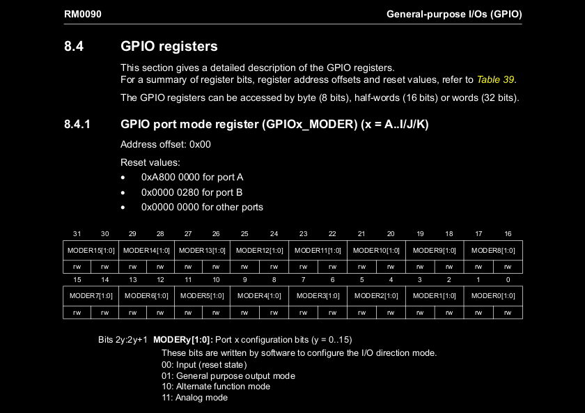
Next on our list is configuring GPIOA8 to be an output. As before, we can look up the base address of GPIOA registers in the ref man. It’s 0x . Then, we can have a read of the GPIO registers to find out which one we need to write to.
It looks like we want GPIOA_MODER, and you can see above that the reset value is 0xA for GPIOA. I understand this is because some of the GPIOA pins are used for the debug interface of the STM , otherwise the reset value would be all zeroes. We want to change the two-bit field MODER8 to be , so we want to set the register value to 0xA . There is no offset this time as the mode register is the first GPIO register.
1) @ Store start address of GPIOA registers 2) movw r0 , # 0x 14 3 movt r0 , # 0x 4 5) @ Use GPIOA_MODER to make GPIOA8 an output 6 movw r1 , # 0x 7 movt r1 , # 0xA 2019 (8) str r1 ) , [r0]
Toggling the GPIO
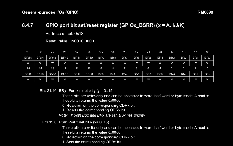
The direction our LED has been wired up means it’s active low, so it will turn on when the GPIO output is cleared, and off when it is set.
So, to turn on our LED we want to set the BR8 field, and to turn it off, we want to set the BS8 field.
1) @ Set BR8 field in GPIOA_BSRR , to clear GPIOA8 2) movw r1 , # 0x 14 3 movt r1 , # 0x 200 4 str r1 ), 5) 6 @ Set BS8 field in GPIOA_BSRR , to set GPIOA8 7 movw r1 , # 0x (8) str r1 ) , Looping
The last code snippet will just turn the LED off and on once. To create an infinite loop instead, we simply create a label (let’s call it . loop and then use the branch instruction to go back to that label!
1) . loop : 2) @ Set BR8 field in
GPIOA_BSRR , to clear GPIOA8 3 movw r1 , # 0x 11 4 movt r1 ), # 0x 415 5) str r1 , 6 7 @ Set BS8 field in GPIOA_BSRR , to set GPIOA8 (8) movw r1 , # 0x (9 str r1 , b . loop Adding a delay
Now for something that is hopefully a lot more interesting than just shoving values into memory addresses. We want to do this in a loop, with a delay between turning the LED off an on!
There are a few ways you could do this delay. If precise timing was important, the timer peripherals of the STM can be used. We could also just add a lot of nop (no operation) over and over again - that doesn't feel very sophisticated, and would give us a really large binary!
We’re going to do this by putting a big number in a register and decrementing it until it hits zero. So, we’re creating another loop, but this time with an exit condition.
1) . loop : 2) @ Set BR8 field in
GPIOA_BSRR , to clear GPIOA8 3 movw r1 , # 0x 11 4 movt r1 ), # 0x 415 5) str r1 , 6 7 @ Delay (8) movw r2 ) , # 0x 9 movt r2 , # 0x c . L 1 : subs r2 , # 0x bne . L 1 [r0] @ Set BS8 field in GPIOA_BSRR , to
set GPIOA8 movw r1 , # 0x 415 str r1 , @ Delay movw r2 , # 0x movt r2 , # 0x 13 c . L 2 : subs r2 , # 0x ( bne . L 2) b . loop
Putting the pieces together
We now have everything we need to flash our LED – almost.
There’s some boilerplate that needs added to our assembly file. We need to give our a name to the entry point, let’s call it main .
There are two instruction encodings for ARM: ARM and Thumb. The encoding defines how the assembly is translated to machine code. It used to be that you needed different syntax for each of these, until ARM brought out their unified assembly language. Line 1 below is telling the assembler (the tool that turns the assembly into machine code) which syntax we are using.
Then, line 3 is telling the assembler that we are using the Thumb encoding for main , which is the only encoding our target (the STM F4) supports. Then line 4 is exposing the symbol main
to the linker.
1) . syntax unified 2) 3 . thumb_func 4 . global main 5) main:
Lastly, we need to make sure our program is what runs when our microcontroller powers on. The reset vector is the location the CPU will go to find the first instruction it will execute after being reset.
What we’re doing below is putting the address of main into the reset vector so that when our board turns on, it will go to that address and start running our code to flash the LED.
1) . section . vector_table . reset_vector 2) . word main
We now have our final asm file:
1) . syntax unified 2) 3 . thumb_func 4 . global main 5) main: 6 @ Store RCC base address in r0 7 movw r0 , # 0x (8) movt r0 , # 0x 9 @ Turn on GPIOA clock by setting bit
0 in AHB1ENR register movw r1 , # 0x str r1 , [r0, #0x30] @ Store start address of GPIOA registers movw r0 , # 0x 14 movt r0 , # 0x @ Use GPIOA_MODER to make GPIOA8 an output movw r1 , # 0x 14 movt r1 , # 0xA str r1 , [r0] . loop : @ Set BR8 field in GPIOA_BSRR , to
clear GPIOA8 movw r1 , # 0x 14 movt r1 , # 0x 415 str r1 , @ Delay movw r2 , # 0x movt r2 , # 0x 13 c . L 1 : subs r2 , # 0x bne . L 1 [r0] @ Set BS8 field in GPIOA_BSRR , to
set GPIOA8 movw r1 , # 0x 415 str r1 , @ Delay movw r2 , # 0x movt r2 , # 0x 13 c . L 2 : subs r2 , # 0x ( bne . L 2)
b . loop . section . vector_table . reset_vector () . word main
We use an assembler
to turn our assembly into an object file, eg
arm-none-eabi-as -mcpu=cortex-m4 toggle. s -c -o output / toggle.o
Then we use a linker to make an executable. We need a custom linker script to Tell the linker where RAM and flash start on our target. Here’s what I used:
1) ENTRY ( main ) 2) 3 MEMORY { 4 FLASH : ORIGIN = 0x , LENGTH = K 5) RAM : ORIGIN = 0x , LENGTH = K 6 } 7 8 SECTIONS { 9 . vector_table ORIGIN ( FLASH ) : { LONG ( ORIGIN ( RAM ) LENGTH ( RAM ) ) ; KEEP ( ( . vector_table ) ) ; } > FLASH . text ADDR ( . vector_table ) ( SIZEOF ( . vector_table ) : { text . text . ) ; } > FLASH }
Then we can call the linker: arm-none-eabi-ld -T link.ld output / toggle.o -o output / toggle
I’m using a Black Magic probe to flash my 1bitsy. I can talk to the probe over gdb:
gdb-multiarch -n –batch -ex ‘tar ext / dev / serial / by-id / example’ -ex ‘mon tpwr en’ -ex ‘mon swdp_scan’ -ex ‘att 1’ -ex ‘load’ -ex ‘start’ -ex ‘detach’ output / toggle
You can check out my GPIO toggling exercise which talks you through the assembly here in a little more detail, and provides a Dockerfile for emulating the target chip. I’ll have a (shorter) blog post about the emulation soon.
Azeria Labs have an An excellent guide
to ARM assembly that goes into more detail than I have, though assumes a bit more knowledge about computer architecture.
The
Cortex M4 User Guide is a good technical reference for the assembly written here
(Read More)
 This is just a simple electronics circuit with current flowing through the LED. We have low voltage at the bottom, and higher voltage at the top: that difference causes current to flow, lighting up our LED. But this is no good for us – we want to control the flow of current so that we can flash our LED on and off.
 Rust and C are also used for embedded work. The C you’d write for embedded would be quite different from what you might write for a desktop application – you likely wouldn’t use any of the STL containers as they all rely on dynamic memory allocation. Eliminating dynamic memory allocation is safer: the risk of memory allocation failing is much higher when there isn’t much memory to begin with. And a failure could be much more catastrophic: many embedded Systems are designed to run autonomously, without any human there to restart them. Many control safety-critical physical systems.
 mov r0, # 5 . This means move the literal value 5 into register 0. But what’s a register? A register is the last key concept we’re going to need to know before we write any assembly.
  – bit registers.
 mov instruction, and then copy 0x into the top half, hence the (t in movt below. str instruction. With these runes, we can enable the clock!
All the mov instructions are about moving data into registers. The str instruction moves data from registers and into memory.
You can read more detail about these instructions in the User Guide for our CPU.
Setting GPIOA8 to an output
Next on our list is configuring GPIOA8 to be an output. As before, we can look up the base address of GPIOA registers in the ref man. It’s 0x . Then, we can have a read of the GPIO registers to find out which one we need to write to.
It looks like we want GPIOA_MODER, and you can see above that the reset value is 0xA for GPIOA. I understand this is because some of the GPIOA pins are used for the debug interface of the STM , otherwise the reset value would be all zeroes. We want to change the two-bit field MODER8 to be , so we want to set the register value to 0xA . There is no offset this time as the mode register is the first GPIO register.
Toggling the GPIO
The direction our LED has been wired up means it’s active low, so it will turn on when the GPIO output is cleared, and off when it is set.
So, to turn on our LED we want to set the BR8 field, and to turn it off, we want to set the BS8 field.
The last code snippet will just turn the LED off and on once. To create an infinite loop instead, we simply create a label (let’s call it . loop and then use the branch instruction to go back to that label!
Now for something that is hopefully a lot more interesting than just shoving values into memory addresses. We want to do this in a loop, with a delay between turning the LED off an on!
There are a few ways you could do this delay. If precise timing was important, the timer peripherals of the STM can be used. We could also just add a lot of nop (no operation) over and over again - that doesn't feel very sophisticated, and would give us a really large binary!
We’re going to do this by putting a big number in a register and decrementing it until it hits zero. So, we’re creating another loop, but this time with an exit condition.
 9 movt r2 , # 0x c . L 1 : subs r2 , # 0x bne . L 1 [r0] @ Set BS8 field in GPIOA_BSRR , to
Putting the pieces together
We now have everything we need to flash our LED – almost.
There’s some boilerplate that needs added to our assembly file. We need to give our a name to the entry point, let’s call it main .
There are two instruction encodings for ARM: ARM and Thumb. The encoding defines how the assembly is translated to machine code. It used to be that you needed different syntax for each of these, until ARM brought out their unified assembly language. Line 1 below is telling the assembler (the tool that turns the assembly into machine code) which syntax we are using.
Then, line 3 is telling the assembler that we are using the Thumb encoding for main , which is the only encoding our target (the STM F4) supports. Then line 4 is exposing the symbol main
to the linker.
Lastly, we need to make sure our program is what runs when our microcontroller powers on. The reset vector is the location the CPU will go to find the first instruction it will execute after being reset.
What we’re doing below is putting the address of main into the reset vector so that when our board turns on, it will go to that address and start running our code to flash the LED.
We now have our final asm file:
9 @ Turn on GPIOA clock by setting bit
We use an assembler
to turn our assembly into an object file, eg
arm-none-eabi-as -mcpu=cortex-m4 toggle. s -c -o output / toggle.o
Then we use a linker to make an executable. We need a custom linker script to Tell the linker where RAM and flash start on our target. Here’s what I used:
 8 SECTIONS { 9 . vector_table ORIGIN ( FLASH ) : { LONG ( ORIGIN ( RAM ) LENGTH ( RAM ) ) ; KEEP ( ( . vector_table ) ) ; } > FLASH . text ADDR ( . vector_table ) ( SIZEOF ( . vector_table ) : { text . text . ) ; } > FLASH }
Then we can call the linker: arm-none-eabi-ld -T link.ld output / toggle.o -o output / toggle
I’m using a Black Magic probe to flash my 1bitsy. I can talk to the probe over gdb:
You can check out my GPIO toggling exercise which talks you through the assembly here in a little more detail, and provides a Dockerfile for emulating the target chip. I’ll have a (shorter) blog post about the emulation soon.
Azeria Labs have an An excellent guide
to ARM assembly that goes into more detail than I have, though assumes a bit more knowledge about computer architecture.
The
Cortex M4 User Guide is a good technical reference for the assembly written here
- (Read More)

GIPHY App Key not set. Please check settings