

What explains the popularity of terminals with 80 × 24 and 80 × 25 displays? A recent blog post “(x)“motivated me to investigate this. The source of 80 – column lines is clearly punch cards, as commonly claimed. But why 24 or 25 lines? There are many theories, but I found a simple answer: IBM, in particular its dominance of the terminal market. In 1971, IBM introduced a terminal with an 80 × 24 display (the 3270) and it soon became the best-selling terminal, forcing competing terminals to match its (×) size. The display for the IBM PC added one more line to its screen, making the 80 × 25 size standard in the PC world. The impact of these systems remains decades later: 80 – character lines are still a standard, along with both 80 × 24 and 80 × 25 terminal windows.
In this blog post, I’ll discuss this history in detail, including some other systems that played key roles. The CRT terminal market essentially started with the IBM (Display Station in 1965, built from curious technologies such as sonic delay lines. This led to the popular IBM 3270 display and then widespread, inexpensive terminals such as the DEC VT 100. In 1981, IBM released a microcomputer called the DataMaster. While the DataMaster is mostly forgotten, it strongly influenced the IBM PC, including the display. This post also studies reports on the terminal market from the 1970 s and 1980 s; these make it clear that market forces, not technological forces, led to the popularity of various display sizes.
Some theories about the 80 × 24 and 80 × 25 sizes
Arguments about terminal sizes go back decades,5but the article(x)presented a detailed and interesting theory. To summarize, it argued that The 80 × 25 display was used because it was compatible with IBM’s 80 – column punch cards,(1)fits nicely on a TV screen with a 4: 3 aspect ratio, and just fit into 2K of RAM. This led to the 80 × 25 size on terminals such as the DEC VT (terminal) 1978). The VT 100 ‘s massive popularity led to it becoming a standard, leading to the ubiquity of 80 × 25 terminals. At least that’s the theory.
It’s true that 80 – column displays were motivated by punch cards4and the VT 100 became a standard,2but the rest of this theory falls apart. The biggest problem with this theory is the VT 100 ‘s display was 80 × 24, not 80 × 25.3In addition, the VT 100 used extra bytes of storage for each line, so the display memory did not fit into 2K. Finally, up until the 1980 s, most displays were 80 × 24, not 80 × 25.
.")
The DEC VT 100 terminal had an 80 × 24 display. Over a million of them were sold. Photo fromJason Scott, (CC BY-SA 4.0).
Other theories have been expressed onSoftware Engineering StackExchangeandRetrocomputing StackExchange, arguing that 80 × 24 terminals resulted from technical reasons such as TV scan rates, aspect ratios, memory sizes, typography, the history of typewriters, and so forth. There is a fundamental problem with theories that (×) is an inevitable consequence of technology, though: terminals in the mid – 1970 s had dozens of diverse screen sizes such as 31 × 11, 42 × 24, 50 × 20, 52 × 48, 81 × 38, 100 × 50, and 133 × 64.This makes it clear that technological limitations didn’t force terminals into a particular size. To the contrary, as technology improved, most of these sizes disappeared and terminals were largely 80 × 24 by the early 1980 s. This illustrates that standardization was the key factor, not the technology.
I’ll briefly summarize why technical factors don’t have much impact on the terminal size. Although US televisions used 525 scan lines and 60 Hz refresh,940% of terminals used other values.6The display frequency and bandwidth didn’t motivate a particular display size because terminals generated characters with a wide variety of matrix sizes.************************** 8Although memory cost was significant, DRAM chip sizes quadrupled every three years, making memory only a temporary constraint. The screen’s aspect ratio wasn’t a big factor because the text’s aspect ratio often didn’t match the screen’s ratio.7Of course technology had some influence, but it didn’t stop early manufacturers from creating terminal sizes ranging from (× 8 to) × 64.
The Rise of CRT terminals
At this point, a bit of history of CRT terminals will help.11Many readers will be familiar with ASCII terminals, such as stand-alone terminals like the DEC VT 100, serial terminal connections via a PC, or the serial port on boards such as the Arduino. This type of terminal has its roots inteleprinters, electro-mechanical keyboard / printers that date back to the early 1900 s. The best-known teleprinter is the Teletype, popular in newsrooms as well as computer systems in the 1970 s. (The Linux device/ dev / ttyis named after the Teletype.) Teletypes typically printed 72 – character lines on a roll of paper.
.")
A Teletype ASR 33 communicated in ASCII and printed 72 characters per line. Hundreds of thousands of these were produced from 1963 to 1981. The punched tape reader and punch is on the left. Photo fromArnold Reinhold, (CC BY-SA 3.0
In the 1970 s, replacing teleprinters with CRT terminals was a large and profitable market. AT&T introduced the Teletype Model 40 in 1973, a CRT terminal with an 80 × 24 display.12Many other companies introduced competing CRT terminals, and “Teletype-compatible” became a market segment. By 198111these terminals were being used in many roles besides replacing teleprinters and the name shifted to “ASCII terminals. ” By 1985, CRT terminals were a huge success with 10 million terminals installed in the US.
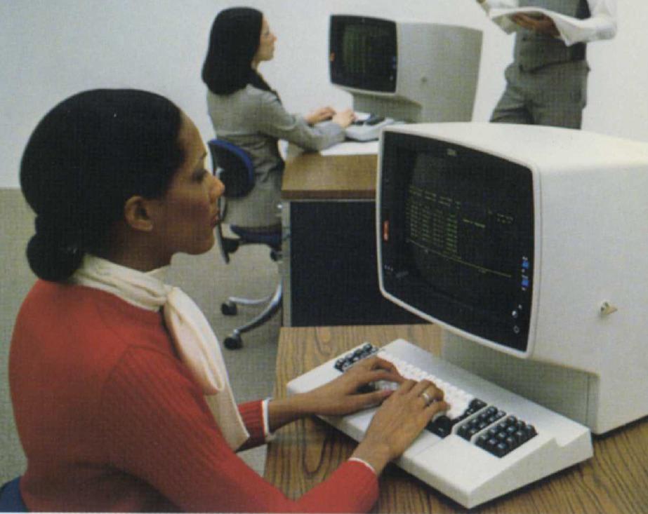
The IBM terminal, specifically the newer 3278 model. From (IBM) *********************************************************************************************************************************************** (Brochure) (1977).
But there’s a parallel world of mainframe terminals, a world that may be unfamiliar to many readers. In 1965, IBM introduced the IBM 2260 Display Terminal, which placed IBM’s “stamp of approval” on the CRT terminal, which had previously been “somewhat of a novelty.”6This terminal dominated the market until IBM replaced it with the cheaper and more advanced IBM (terminal in) . Unlike asynchronous ASCII terminals that transmitted individual keystrokes, these terminals wereblock oriented, efficiently exchanging large blocks of characters with a mainframe. The 3270 terminal was fairly ” intelligent “: a 3270 user could fill in labeled fields on the screen, and then transmit all the data at once by pressing the “Enter” key. (This is why modern keyboards often still have the “Enter” key.) Sending a block of data was more efficient than sending each keystroke to the computer, and allowed mainframes to support hundreds of terminals. In the next sections, I’ll discuss the 2260 and 3270 terminals in detail.
The chart below6shows how the terminal market looked in 1974. The market was ruled by IBM’s 3270 terminal, which had obsoleted IBM’s 2260 terminal by this point. With 50% of the market, IBM essentially defined the characteristics of a CRT terminal. Teleprinter replacement was a large and influenetial market; the Teletype Model 40 was small but growing in importance. Although DEC would soon be a major player, it was in the small “Independent Systems” slice at this point.
. From Alphanumeric and Graphic CRT Terminals.")
The IBM 2260 video display terminal
The IBM 2260 was introduced in 1965 and was one of the first video display terminals.14It filled three roles: remote data entry (in place of punching cards), inquiry (e.g. looking up records in a database), and as a system console. This compact terminal weighed 45 pounds and was sized to fit on a standard office typewriter stand. Note the thickness of the keyboard; it reused the complex keyboard mechanism of the IBM keypunch.13

IBM 2260 Display Station. Photo from IBM viaFrank da Cruz.
You might wonder how IBM could produce such a compact terminal with 1965 technology. The trick was that the terminal held just the keyboard and CRT display; all the control logic, character generation, storage, and interfacing was in a massive 1000 pound cabinet (below).15This cabinet contained the circuitry to handle up to 24 display terminals. It generated the pixels for these terminals and send video signals to the terminals, which could be up to 2000 feet away.

The IBM 2848 Display Control could drive up to 24 display terminals. The cabinet was 5 feet wide and weighed 1000 pounds.
One of the most interesting features of the 2260 is the sonic delay lines used for pixel storage. Bits were stored as sound pulses sent into a nickel wire, about 50 feet long. The pulses traveled through the wire and came out the other end exactly 5. 5545 milliseconds later. By sending a pulse (or not sending a pulse for a 0) every 500 nanoseconds, the wire held 11, 008 bits. A pair of wires created a buffer that held the pixels for (characters.)16
The sonic delay line had several problems. First, you had to constantly refresh the data: as bits came out one end of the wire, you had to feed them back in the other end. Second, the delay line was not random access: if you wanted to update a character, you needed to wait several milliseconds for those bits to circulate. Third, the delay line was sensitive to vibration;Wikipediasays that heavy footsteps could mess up the screen. Fourth, the delay line speed was sensitive to temperature changes; it needed to warm up for two hours in a temperature-controlled cabinet before use. With all these disadvantages, you might wonder why sonic delay lines were used. The main reason was they were much cheaper than core memory. The serial nature of a delay line was also a good match to the serial nature of a raster-scan display.

The image below shows the screen of the 2260 Model 2, with 12 lines of 40 characters. (The Model 1 had 6 lines of 40 characters and the Model 3 had 12 lines of 80 characters.) Notice that the lines are double-spaced; this is because the control unit actually generated 24 lines of text but alternating lines went to two different terminals.20This is a very strange approach, but it split the high cost of the control hardware across two terminals.19Another strange characteristic was that the 2260 ‘s scan lines were vertical, unlike the horizontal scan lines in almost every video display and television.21

IBM 2260 display showing 12 lines of 40 characters. Image from2260 Operator Manual.
Each character was represented in 6-bit EBCDIC, giving a character set of 64 characters (no lower-case).18The delay lines stored the pixels to be displayed, but they also stored the EBCDIC code for each character. The trick here is the blank column of pixels between each character for horizontal spacing between characters. The system used this column to store the BCD character value but blanked the display during this column so the BCD value didn’t show up as pixels on the screen. This allowed the 6-bit character value to be stored essentially for free.
The relevant question is why did the 2260 have a display with 12 lines of 80 characters?.") 2324The 80 – character width allowed the terminals to take the place of 80 – column punch cards for data entry. (In the 40 – character models, a card would be split across two lines.) As for the 12 lines, that appears to be what the delay lines could support without flicker.22
2324The 80 – character width allowed the terminals to take the place of 80 – column punch cards for data entry. (In the 40 – character models, a card would be split across two lines.) As for the 12 lines, that appears to be what the delay lines could support without flicker.22

The IBM 2260 was a big success, and led to the popularity of the CRT terminal. The impact of the IBM 2260 terminal is shown by a1974 report on terminals; about 50 terminals were listed as compatible with the IBM 2260. The IBM 2260 didn’t have an 80 × 24 display (although it generated 80 × 24 internally), but its 40 × 12 and 80 × 12 displays made× 24 the next step for IBM.
The IBM 3270 video display
In 1971, IBM released the IBM 3270 video display system, which proceeded to dominate the market for CRT terminals.26This terminal supported a 40 × 12 display to provide a migration path from the 2260, but also supported a larger 80 × 24 display. The 3270 had more features than The 2260, such as protected fields on the screen, more efficient communication modes, and variable-intensity text. It was also significantly cheaper than the 2260, ensuring its popularity.25*****
.")
The IBM 3270 terminal. The Selector Light Pen w as used to select data fields, somewhat like a mouse. This terminal is a later model, the 3278; in the photo it is displaying 43 lines of 80 characters. From (IBM) *********************************************************************************************************************************************** (Brochure) (1977).
The technology in the 3270 was a generation more advanced than the 2260, replacing vacuum tubes and transistors with hybridSLT modules, similar to integrated circuits. Instead of sonic delay lines, it used 480 – bit MOS shift registers.27The 40 × 12 model used one bank of shift registers to store 480 characters. In the larger model, four banks of shift registers (1920 characters) supported an 80 × 24 display. In other words, the 3270 ‘s storage was in 480 – character blocks for compatibility with the 2260, and using four blocks resulted in the 80 × 24 display. (Unlike RAM chips, a shift register size didn’t need to be a power of 2. While a RAM chip is arranged as a matrix, a shift register has a serpentine layout (below) and can be an arbitrary size.)

Die photo of the (Intel) shift register. This shift register was not used in the IBM 3270 but was used in other terminals such as the Datapoint 2200.
IBM provided extensive software support for the 3270 terminal.28This had an important impact on the terminal market, since it forced other manufacturers to build compatible terminals if they wanted to compete. In particular, this made 3270 -compatibility and the 80 × 24 display into a de facto standard. In 1977, IBM introduced the 3278, an improved 3270 terminal that supported 12, 24, 32, or 43 lines of data. It also added a status line, called the “operator information area”. The new 32 – and 43 – line sizes didn’t really catch on, but the status line became a common feature on competing terminals.
Looking at industry reports(6) ****1132shows the popularity of various terminal sizes from the 1970 s to the 1990 s. Although there were 80 × 25 displays in 1970 (if not earlier), The 80 × 24 display was much more common. The wide variety of terminal sizes in 1974 diminished over time, with the market converging on 80 × 24. By 1979, the DEC VT 100 (with its 80 × 24 display) was the most popular ASCII terminal with over 1 million sold. Terminals started supporting 132 × 24 for compatibility with 132 – character line printers,29especially as larger 15 ” monitors became more affordable, but (×) remained the most popular size. Even by1991, 80 × 25 remained relatively uncommon.
The IBM PC and the popularity of 80 × 25
Given the historical popularity of 80 × 24 terminals, why do so many modern systems use 80 × 25 Windows? That’s also due to IBM: The 80 × 25 displaybecame popularwith the introduction of the IBM PC in 1981. The PC’s default display card (MDA) provided 80 × 25 monochrome text while theCGAcard provided 40 × 25 and 80 × 25 in color. This became the default size of a Windows console, as well as the typical size for PC-based terminal windows.
 card. Photo from Boffy b (CC BY-SA 3.0).")
The IBM PC with an 80 × 25 display generated by the MDA (Monochrome Display Adapter) card. Photo fromBoffy b(CC BY-SA 3.0).
Other popular computers at the time used 24 lines , such as the Osborne 1 and Apple II, so I was curious why the IBM PC used 25 lines. To find out, I talked to Dr. Dave Bradley and Prof. Mark Dean, two of the original IBM PC engineers. They explained that the IBM PC was a follow-on to the rather obscure IBM DataMaster office computer,30and many of the IBM PC design choices followed the DataMaster microcomputer. The IBM PC kept the DataMaster’s keyboard, but detached from the main unit. Both systems used BASIC, but the decision to get the PC’s BASIC interpreter from the tiny company Microsoft would change both companies more than anyone could imagine. Both systems went with an Intel processor, an 8-bit 8085 in the DataMaster and the 16 – bit 8088 in the IBM PC. They also used the same interrupt controller, DMA controller, parallel port, and timer chips. The PC’s 62 – pinexpansion buswas almost identical to DataMaster’s.

The IBM DataMaster System / 23 was a microcomputer announced in 1981 just a month before the IBM PC.
The drawing below is part of an early design plan for the IBM PC. In particular, the IBM PC was going to use the 80 × 24 display of the DataMaster (codenamed LOMA), as well as 40 × 16 and 60 × 16 more suitable for televisions. The drawings also show color graphics with 280 × 192 pixels, the same resolution as the Apple II. But the IBM PC ended up not quite matching this plan.
 design plan for the IBM PC.")
Detail from an early (August 25, 1980) design plan for the IBM PC. “LOMA” is the code name for the IBM DataMaster. ” (kHz “is the) . 432 kHz horizontal scan frequency used by the MDA card, providing more resolution than the 15. 750 kHz used by NTSC televisions. Scan courtesy of Dr. Dave Bradley.
The designers of the IBM PC managed to squeeze a few more pixels onto the display to get 320 × 200 pixels. When using an 8 × 8 character matrix, the updated graphics mode supported 40 × 25 text, while the double-resolution graphics mode with 640 × 200 pixels supported 80 × 25 text. The monochrome graphics card (MDA) matched this (×) size. In other words, the IBM PC ended up using 80 × 25 text because the display provided enough pixels, and it provided differentiation from other systems, but there wasn’t an overriding motivation. In particular, the designers of the PC weren’t constrained by compatibility with other IBM systems.31
Conclusion
To summarize, many theories have been proposed giving technical reasons why 80 × 24 (or 80 × 25) is the n atural size for a display. I think the wide variety of display sizes in the early 1970 s proves this technological motivation is mostly wrong. Instead, display sizes converged on what IBM produced, first with the punch card, then the IBM 2260 terminal, the IBM 3270, and finally the IBM PC. The 72 – column Teletype had some influence on terminal sizes at first, but this size was also swept away by IBM compatibility. The result is the current situation with an uneasy split between 80 × 24 and 80 × 25 standards.
Thanks to Dr. Dave Bradley, Prof. Mark Dean, and IBM engineerIggy Menendezfor information. I announce my latest blog posts on twitter, so follow me@ kenshirrifffor future articles . I also have anRSS feed.
Notes and References

(Read More)


GIPHY App Key not set. Please check settings