In this clip the Chernobyl Dice set to continuously generate numbers in the range [1,26]. You can check out a longer YouTube clip showing various modes of here:https://youtu.be/8uue9Aae9ss
************************** Description
The Chernobyl Dice is a quantum random number generator [0] that uses nuclear decays from a weakly radioactive sample as a source of entropy. It consists of four primary components:
An Arduino Nano microcontroller
A Geiger counter
The Chernobyl Dice is a quantum random number generator [0] that uses nuclear decays from a weakly radioactive sample as a source of entropy. It consists of four primary components:
- An Arduino Nano microcontroller
- A Geiger counter
WARNING: These instructions and resources are not polished and are somewhat untested. This is a project for advanced makers, and you should fully expect to have a bit of an adventure while building your own Chernobyl Dice! That said: Shoot me a message if you run into trouble, and I’ll try to help you out and improve the instructions as well.
Here’s a rough outline of the steps required for assembly:
Print or fabricate the following custom parts from files in the GitHub repository
- Enclosure (using 3D printer or 3D printing service)
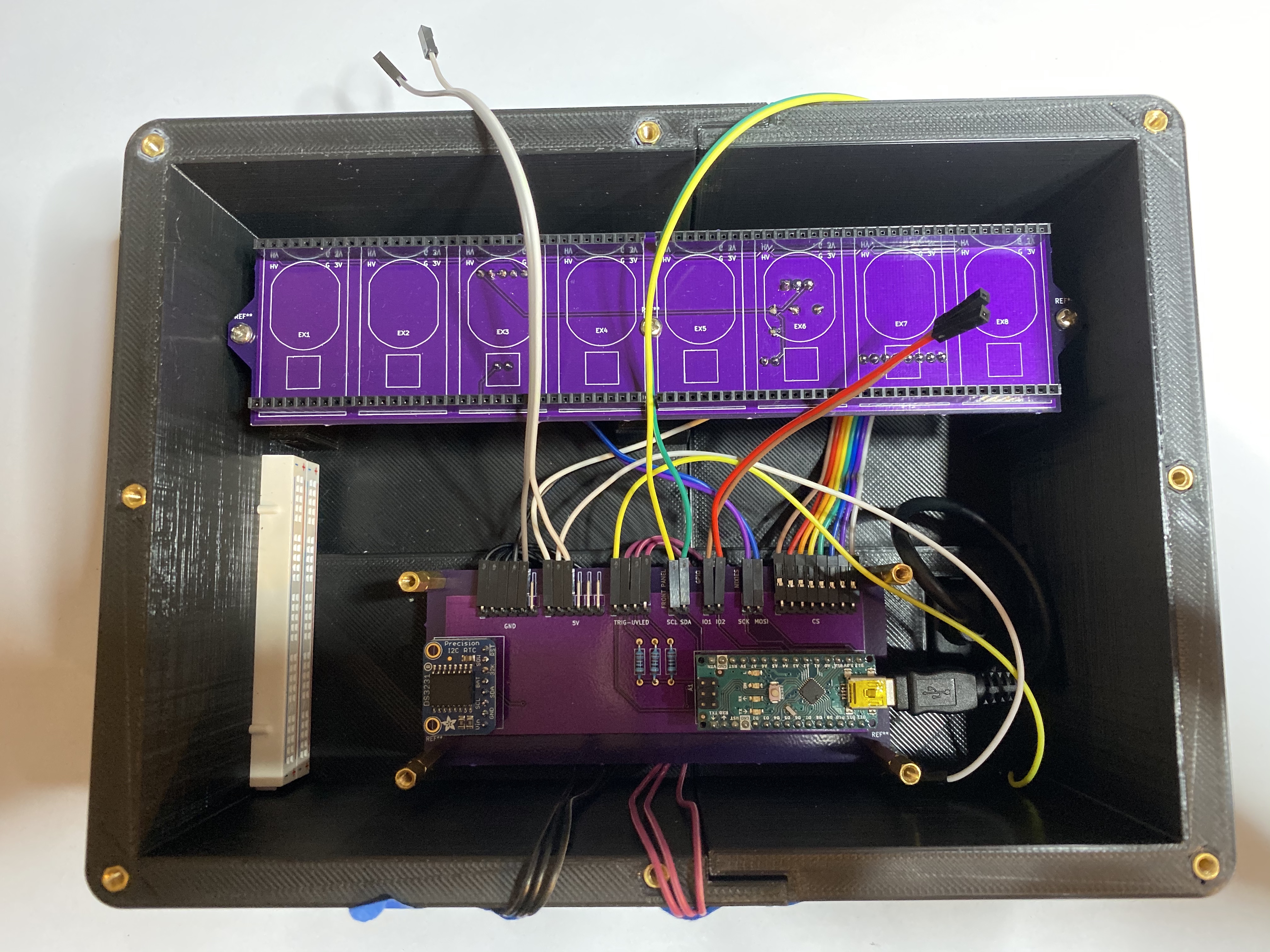
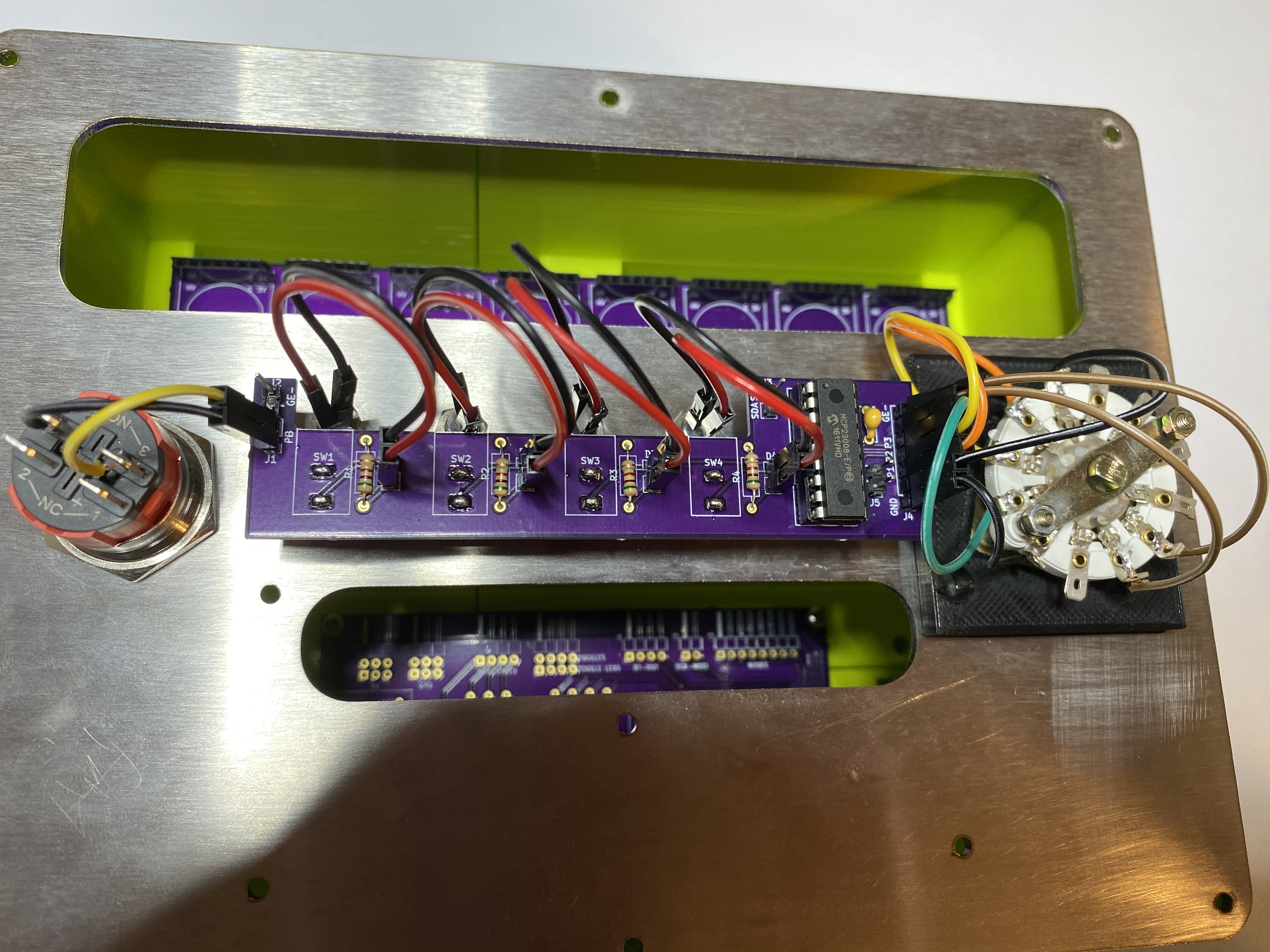
- Logic, Nixie Display, and Control Panel Custom PCBs (using a board fabrication service such as OSHPark) Stainless steel front panel (using a service such as OSHCut)
- Acrylic back panel (using a service such as Sculpeo) (******************************
Order other components (see URLs in the parts list)
Embed brass standoffs into enclosure (this is how front and back panels and custom PCBs will be mounted)
TIPS
A single drop of cyanocrylate (superglue) should be placed in the standoff holes in the enclosure before they are pressed in (the tip of a Phillips head screw driver works well for this task)
If the tops some holes came out of the printer a bit distorted then they can be widened easily by twisting a largish Phillips head screwdriver in them until the top of the hole is wide enough.
Assemble custom PCBs and ‘exixe’ nixie tube driver boards using build photos as a guide
TIPS
The female headers on the Nixie Display Board for the nixie tube driver PCBs can be assembled using only four long female header strips (eg there’s no need to separately attach sixteen 7-pin female headers — see photos)
The “CS” 8-pin male header is a currently a tight fit, so you will probably need to use needle noise pliers to push the pins through the board
For the control panel PCB you can temporarily mount the toggle switches in the front panel and then press the PCB on top of the back of the switches to ensure good alignment — you can then pull the whole board-and-toggle assembly off of the front panel to solder it, or even solder it in place and then pull it off
The file ‘nixie_holder.stl’ is a provided as a useful place to rest the nixie tube while soldering them to the ‘exixe’ driver boards
Attach the acrylic back panel and panel mount USB cable to the rear of the enclosure
Mount custom PCBs inside enclosure and perform wiring (see wiring schematic and build photos)
Partially dis-assemble rotary switch to attach it to the “lock plate” (lock_plate.stl)
Perform any necessary finishing to the stainless steel front panel
TIPS
Some mounting holes for toggles and switches may need to be widened (use a round file for this)
Surface finish of a laser cut part can be improved by sanding (with the grain) ******************************** (using ~) **************************************************************************************************************************************************** (grit sandpaper) test on the back side first)
Mount toggle-and-PCB assembly, LED-with-holder assemblies, rotary-switch-and-lock-plate assembly, and pushbutton on front panel
TIP
While attaching the LED to the holder, apply a drop of cyanocrylate (superglue) to prevent the LED from falling out of the front of the holder
Perform wiring of the control panel (see wiring schematic and build photos)
Fit the eight nixie display driver boards into the female headers of the Nixie Display Board
Wire the Control Panel to the Logic Board
Mount the front panel to the enclosure, taking care to insure that the hole in the rotary switch lock plate lines up with the upper-left standoff on the front of the radioactive sample holder
**************************************** (Standoff Size Guide) *************************************************
(**************************************************** (Location) **************************************************** (Standoff Length) (Type) (******************************************************** (****************************************************** (Rear of enclosure)
(mm) (Female-Female) ********************************************************** (****************************************** Front of enclosure
(mm) (Female-Female) ********************************************************** (****************************************** Nixie Display Board mount**************************************
(mm) ********************************************************** (Female-Female) ********************************************************** (****************************************** Logic Board mount**************************************
(mm) (Female-Female) ********************************************************** (****************************************** (Logic Board-to-Geiger Board)
(mm) ********************************************************** (Male-Female) ********************************************************** (****************************************** (Geiger Board-to-Bottom of Uranium Sample Box) **********************************************************
(mm) (Male-Female) **********************************************************Bottom of Uranium Sample Box-to-Top of Uranium Sample Box (********************************************************** (6 mm) ********************************************************** (Male-Female) ********************************************************** (****************************************** (Top of Uranium Sample Box-to-Front Panel) ********************************************************** (6 mm) ********************************************************** (Male-Female) ********************************************************** (**********************************************************
NOTE: For large internal standoff distances (eg the Nixie Display mount) two standoffs can be stacked to achieve the desired distance.
******************* Wiring Diagram
****************************************
How connect the internal wiring of the Chernobyl Dice.
********************** Build Photos
Enclosure with Standoffs Inserted
(******************************************************************
**********
You can ignore the white breadboards on the left of the enclosure. These assisted in an earlier iteration of the project and are not needed for assembly.Click herefor larger photo.
(Logic Board Mounted) ************************************************
**********
Note the wires for UV LED array are run beneath the logic board. Click here
for larger photo.
(Nixie Display Board Wiring) ************************************************
Click herefor larger photo.
(Nixie Display Board Mounted and Logic Board Wiring) ********************************************
(**************************************************************************
Click herefor larger photo.
(Geiger Board Mounted) ************************************************
(******************************************************************************
NOTE: You must pull the JMP2 jumper near the center of the Geiger board (this turns off the built-in speaker of the board — we want these clicks to be optional and controlled by firmware instead). Click herefor larger photo.
Uranium Sample Holder Lower Half Detail
(**********************************************************************************
UV LEDs and piezo speaker are glued mounted into place using cyanocrylate (superglue) adhesive. Uranium glass marbles will be held in place mechanically when the top half is mounted. (Click herefor larger photo.
Uranium Sample Holder Lower Half Mounted
(**************************************************************************************
The middle standoff is attached on the underside with a nut. (Click herefor larger photo.
Uranium Sample Holder Top Half Mounted
() ****************************************************************************************
(Click herefor larger photo.
(Control Panel Board Wired) *************************************************
(Click herefor larger photo.
(Control Panel Board Wiring Detail) **********************************************
Click herefor larger photo.
Acknowledgment
Many thanks to Emily Velasco (@ MLE_Online
for advice on stainless steel surface sanding, and for generally being enthusiastic as heck about this project.
References
[0] “Quantum Random Number Generators.” M. Herrero-Collantes and J. C. Garcia-Escartin.https://arxiv.org/abs/ 2019. 212667
[1] “A Statistical Test Suite for Random and Pseudorandom Number Generators for Cryptographic Applications.”https://csrc.nist.gov/publications/detail/sp/ – / rev-1a / final
Order other components (see URLs in the parts list)
Embed brass standoffs into enclosure (this is how front and back panels and custom PCBs will be mounted)
- TIPS
- A single drop of cyanocrylate (superglue) should be placed in the standoff holes in the enclosure before they are pressed in (the tip of a Phillips head screw driver works well for this task)
- If the tops some holes came out of the printer a bit distorted then they can be widened easily by twisting a largish Phillips head screwdriver in them until the top of the hole is wide enough.
Assemble custom PCBs and ‘exixe’ nixie tube driver boards using build photos as a guide
- TIPS
- The female headers on the Nixie Display Board for the nixie tube driver PCBs can be assembled using only four long female header strips (eg there’s no need to separately attach sixteen 7-pin female headers — see photos)
- The “CS” 8-pin male header is a currently a tight fit, so you will probably need to use needle noise pliers to push the pins through the board
- For the control panel PCB you can temporarily mount the toggle switches in the front panel and then press the PCB on top of the back of the switches to ensure good alignment — you can then pull the whole board-and-toggle assembly off of the front panel to solder it, or even solder it in place and then pull it off
- The file ‘nixie_holder.stl’ is a provided as a useful place to rest the nixie tube while soldering them to the ‘exixe’ driver boards
Attach the acrylic back panel and panel mount USB cable to the rear of the enclosure
Mount custom PCBs inside enclosure and perform wiring (see wiring schematic and build photos)
Partially dis-assemble rotary switch to attach it to the “lock plate” (lock_plate.stl)
Perform any necessary finishing to the stainless steel front panel
TIPS
Some mounting holes for toggles and switches may need to be widened (use a round file for this)
Surface finish of a laser cut part can be improved by sanding (with the grain) ******************************** (using ~) **************************************************************************************************************************************************** (grit sandpaper) test on the back side first)
Mount toggle-and-PCB assembly, LED-with-holder assemblies, rotary-switch-and-lock-plate assembly, and pushbutton on front panel
TIP
While attaching the LED to the holder, apply a drop of cyanocrylate (superglue) to prevent the LED from falling out of the front of the holder
Perform wiring of the control panel (see wiring schematic and build photos)
Fit the eight nixie display driver boards into the female headers of the Nixie Display Board
Wire the Control Panel to the Logic Board
Mount the front panel to the enclosure, taking care to insure that the hole in the rotary switch lock plate lines up with the upper-left standoff on the front of the radioactive sample holder
**************************************** (Standoff Size Guide) *************************************************
(**************************************************** (Location) **************************************************** (Standoff Length) (Type) (******************************************************** (****************************************************** (Rear of enclosure)
(mm) (Female-Female) ********************************************************** (****************************************** Front of enclosure
(mm) (Female-Female) ********************************************************** (****************************************** Nixie Display Board mount**************************************
(mm) ********************************************************** (Female-Female) ********************************************************** (****************************************** Logic Board mount**************************************
(mm) (Female-Female) ********************************************************** (****************************************** (Logic Board-to-Geiger Board)
(mm) ********************************************************** (Male-Female) ********************************************************** (****************************************** (Geiger Board-to-Bottom of Uranium Sample Box) **********************************************************
(mm) (Male-Female) **********************************************************Bottom of Uranium Sample Box-to-Top of Uranium Sample Box (********************************************************** (6 mm) ********************************************************** (Male-Female) ********************************************************** (****************************************** (Top of Uranium Sample Box-to-Front Panel) ********************************************************** (6 mm) ********************************************************** (Male-Female) ********************************************************** (**********************************************************
NOTE: For large internal standoff distances (eg the Nixie Display mount) two standoffs can be stacked to achieve the desired distance.
******************* Wiring Diagram
****************************************
How connect the internal wiring of the Chernobyl Dice.
********************** Build Photos
Enclosure with Standoffs Inserted
(******************************************************************
**********
You can ignore the white breadboards on the left of the enclosure. These assisted in an earlier iteration of the project and are not needed for assembly.Click herefor larger photo.
(Logic Board Mounted) ************************************************
**********
Note the wires for UV LED array are run beneath the logic board. Click here
for larger photo.
(Nixie Display Board Wiring) ************************************************
Click herefor larger photo.
(Nixie Display Board Mounted and Logic Board Wiring) ********************************************
(**************************************************************************
Click herefor larger photo.
(Geiger Board Mounted) ************************************************
(******************************************************************************
NOTE: You must pull the JMP2 jumper near the center of the Geiger board (this turns off the built-in speaker of the board — we want these clicks to be optional and controlled by firmware instead). Click herefor larger photo.
Uranium Sample Holder Lower Half Detail
(**********************************************************************************
UV LEDs and piezo speaker are glued mounted into place using cyanocrylate (superglue) adhesive. Uranium glass marbles will be held in place mechanically when the top half is mounted. (Click herefor larger photo.
Uranium Sample Holder Lower Half Mounted
(**************************************************************************************
The middle standoff is attached on the underside with a nut. (Click herefor larger photo.
Uranium Sample Holder Top Half Mounted
() ****************************************************************************************
(Click herefor larger photo.
(Control Panel Board Wired) *************************************************
(Click herefor larger photo.
(Control Panel Board Wiring Detail) **********************************************
Click herefor larger photo.
Acknowledgment
Many thanks to Emily Velasco (@ MLE_Online
for advice on stainless steel surface sanding, and for generally being enthusiastic as heck about this project.
References
[0] “Quantum Random Number Generators.” M. Herrero-Collantes and J. C. Garcia-Escartin.https://arxiv.org/abs/ 2019. 212667
[1] “A Statistical Test Suite for Random and Pseudorandom Number Generators for Cryptographic Applications.”https://csrc.nist.gov/publications/detail/sp/ – / rev-1a / final
Attach the acrylic back panel and panel mount USB cable to the rear of the enclosure
Mount custom PCBs inside enclosure and perform wiring (see wiring schematic and build photos)
Partially dis-assemble rotary switch to attach it to the “lock plate” (lock_plate.stl)
Perform any necessary finishing to the stainless steel front panel
- TIPS
- Some mounting holes for toggles and switches may need to be widened (use a round file for this)
- Surface finish of a laser cut part can be improved by sanding (with the grain) ******************************** (using ~) **************************************************************************************************************************************************** (grit sandpaper) test on the back side first)
Mount toggle-and-PCB assembly, LED-with-holder assemblies, rotary-switch-and-lock-plate assembly, and pushbutton on front panel
TIP
While attaching the LED to the holder, apply a drop of cyanocrylate (superglue) to prevent the LED from falling out of the front of the holder
Perform wiring of the control panel (see wiring schematic and build photos)
Fit the eight nixie display driver boards into the female headers of the Nixie Display Board
Wire the Control Panel to the Logic Board
Mount the front panel to the enclosure, taking care to insure that the hole in the rotary switch lock plate lines up with the upper-left standoff on the front of the radioactive sample holder
**************************************** (Standoff Size Guide) *************************************************
(**************************************************** (Location) **************************************************** (Standoff Length) (Type) (******************************************************** (****************************************************** (Rear of enclosure)
(mm) (Female-Female) ********************************************************** (****************************************** Front of enclosure
(mm) (Female-Female) ********************************************************** (****************************************** Nixie Display Board mount**************************************
(mm) ********************************************************** (Female-Female) ********************************************************** (****************************************** Logic Board mount**************************************
(mm) (Female-Female) ********************************************************** (****************************************** (Logic Board-to-Geiger Board)
(mm) ********************************************************** (Male-Female) ********************************************************** (****************************************** (Geiger Board-to-Bottom of Uranium Sample Box) **********************************************************
(mm) (Male-Female) **********************************************************Bottom of Uranium Sample Box-to-Top of Uranium Sample Box (********************************************************** (6 mm) ********************************************************** (Male-Female) ********************************************************** (****************************************** (Top of Uranium Sample Box-to-Front Panel) ********************************************************** (6 mm) ********************************************************** (Male-Female) ********************************************************** (**********************************************************
NOTE: For large internal standoff distances (eg the Nixie Display mount) two standoffs can be stacked to achieve the desired distance.
******************* Wiring Diagram
****************************************
How connect the internal wiring of the Chernobyl Dice.
********************** Build Photos
Enclosure with Standoffs Inserted
(******************************************************************
**********
You can ignore the white breadboards on the left of the enclosure. These assisted in an earlier iteration of the project and are not needed for assembly.Click herefor larger photo.
(Logic Board Mounted) ************************************************
**********
Note the wires for UV LED array are run beneath the logic board. Click here
for larger photo.
(Nixie Display Board Wiring) ************************************************
Click herefor larger photo.
(Nixie Display Board Mounted and Logic Board Wiring) ********************************************
(**************************************************************************
Click herefor larger photo.
(Geiger Board Mounted) ************************************************
(******************************************************************************
NOTE: You must pull the JMP2 jumper near the center of the Geiger board (this turns off the built-in speaker of the board — we want these clicks to be optional and controlled by firmware instead). Click herefor larger photo.
Uranium Sample Holder Lower Half Detail
(**********************************************************************************
UV LEDs and piezo speaker are glued mounted into place using cyanocrylate (superglue) adhesive. Uranium glass marbles will be held in place mechanically when the top half is mounted. (Click herefor larger photo.
Uranium Sample Holder Lower Half Mounted
(**************************************************************************************
The middle standoff is attached on the underside with a nut. (Click herefor larger photo.
Uranium Sample Holder Top Half Mounted
() ****************************************************************************************
(Click herefor larger photo.
(Control Panel Board Wired) *************************************************
(Click herefor larger photo.
(Control Panel Board Wiring Detail) **********************************************
Click herefor larger photo.
Acknowledgment
Many thanks to Emily Velasco (@ MLE_Online
for advice on stainless steel surface sanding, and for generally being enthusiastic as heck about this project.
References
[0] “Quantum Random Number Generators.” M. Herrero-Collantes and J. C. Garcia-Escartin.https://arxiv.org/abs/ 2019. 212667
[1] “A Statistical Test Suite for Random and Pseudorandom Number Generators for Cryptographic Applications.”https://csrc.nist.gov/publications/detail/sp/ – / rev-1a / final
Mount toggle-and-PCB assembly, LED-with-holder assemblies, rotary-switch-and-lock-plate assembly, and pushbutton on front panel
- TIP
- While attaching the LED to the holder, apply a drop of cyanocrylate (superglue) to prevent the LED from falling out of the front of the holder
Perform wiring of the control panel (see wiring schematic and build photos)
Fit the eight nixie display driver boards into the female headers of the Nixie Display Board
Wire the Control Panel to the Logic Board
Mount the front panel to the enclosure, taking care to insure that the hole in the rotary switch lock plate lines up with the upper-left standoff on the front of the radioactive sample holder
**************************************** (Standoff Size Guide) *************************************************
(**************************************************** (Location) **************************************************** (Standoff Length) (Type) (******************************************************** (****************************************************** (Rear of enclosure)
(mm) (Female-Female) ********************************************************** (****************************************** Front of enclosure
(mm) (Female-Female) ********************************************************** (****************************************** Nixie Display Board mount**************************************
(mm) ********************************************************** (Female-Female) ********************************************************** (****************************************** Logic Board mount**************************************
(mm) (Female-Female) ********************************************************** (****************************************** (Logic Board-to-Geiger Board)
(mm) ********************************************************** (Male-Female) ********************************************************** (****************************************** (Geiger Board-to-Bottom of Uranium Sample Box) **********************************************************
(mm) (Male-Female) **********************************************************Bottom of Uranium Sample Box-to-Top of Uranium Sample Box (********************************************************** (6 mm) ********************************************************** (Male-Female) ********************************************************** (****************************************** (Top of Uranium Sample Box-to-Front Panel) ********************************************************** (6 mm) ********************************************************** (Male-Female) ********************************************************** (**********************************************************
NOTE: For large internal standoff distances (eg the Nixie Display mount) two standoffs can be stacked to achieve the desired distance.
******************* Wiring Diagram
****************************************
How connect the internal wiring of the Chernobyl Dice.
********************** Build Photos
Enclosure with Standoffs Inserted
(******************************************************************
**********
You can ignore the white breadboards on the left of the enclosure. These assisted in an earlier iteration of the project and are not needed for assembly.Click herefor larger photo.
(Logic Board Mounted) ************************************************
**********
Note the wires for UV LED array are run beneath the logic board. Click here
for larger photo.
(Nixie Display Board Wiring) ************************************************
Click herefor larger photo.
(Nixie Display Board Mounted and Logic Board Wiring) ********************************************
(**************************************************************************
Click herefor larger photo.
(Geiger Board Mounted) ************************************************
(******************************************************************************
NOTE: You must pull the JMP2 jumper near the center of the Geiger board (this turns off the built-in speaker of the board — we want these clicks to be optional and controlled by firmware instead). Click herefor larger photo.
Uranium Sample Holder Lower Half Detail
(**********************************************************************************
UV LEDs and piezo speaker are glued mounted into place using cyanocrylate (superglue) adhesive. Uranium glass marbles will be held in place mechanically when the top half is mounted. (Click herefor larger photo.
Uranium Sample Holder Lower Half Mounted
(**************************************************************************************
The middle standoff is attached on the underside with a nut. (Click herefor larger photo.
Uranium Sample Holder Top Half Mounted
() ****************************************************************************************
(Click herefor larger photo.
(Control Panel Board Wired) *************************************************
(Click herefor larger photo.
(Control Panel Board Wiring Detail) **********************************************
Click herefor larger photo.
Acknowledgment
Many thanks to Emily Velasco (@ MLE_Online
for advice on stainless steel surface sanding, and for generally being enthusiastic as heck about this project.
References
[0] “Quantum Random Number Generators.” M. Herrero-Collantes and J. C. Garcia-Escartin.https://arxiv.org/abs/ 2019. 212667
[1] “A Statistical Test Suite for Random and Pseudorandom Number Generators for Cryptographic Applications.”https://csrc.nist.gov/publications/detail/sp/ – / rev-1a / final
Perform wiring of the control panel (see wiring schematic and build photos)
Fit the eight nixie display driver boards into the female headers of the Nixie Display Board
Wire the Control Panel to the Logic Board
Mount the front panel to the enclosure, taking care to insure that the hole in the rotary switch lock plate lines up with the upper-left standoff on the front of the radioactive sample holder
**************************************** (Standoff Size Guide) *************************************************
(**************************************************** (Location) **************************************************** (Standoff Length) (Type) (******************************************************** (****************************************************** (Rear of enclosure)
(mm) (Female-Female) ********************************************************** (****************************************** Front of enclosure (mm) (Female-Female) ********************************************************** (****************************************** Nixie Display Board mount************************************** (mm) ********************************************************** (Female-Female) ********************************************************** (****************************************** Logic Board mount************************************** (mm) (Female-Female) ********************************************************** (****************************************** (Logic Board-to-Geiger Board) (mm) ********************************************************** (Male-Female) ********************************************************** (****************************************** (Geiger Board-to-Bottom of Uranium Sample Box) ********************************************************** (mm) (Male-Female) **********************************************************Bottom of Uranium Sample Box-to-Top of Uranium Sample Box (********************************************************** (6 mm) ********************************************************** (Male-Female) ********************************************************** (****************************************** (Top of Uranium Sample Box-to-Front Panel) ********************************************************** (6 mm) ********************************************************** (Male-Female) ********************************************************** (**********************************************************NOTE: For large internal standoff distances (eg the Nixie Display mount) two standoffs can be stacked to achieve the desired distance.
******************* Wiring Diagram
****************************************
How connect the internal wiring of the Chernobyl Dice.
********************** Build Photos
Enclosure with Standoffs Inserted
(******************************************************************
**********
You can ignore the white breadboards on the left of the enclosure. These assisted in an earlier iteration of the project and are not needed for assembly.Click herefor larger photo.
(Logic Board Mounted) ************************************************
**********
Note the wires for UV LED array are run beneath the logic board. Click here
for larger photo.
********************** Build Photos
Enclosure with Standoffs Inserted
(******************************************************************
**********
You can ignore the white breadboards on the left of the enclosure. These assisted in an earlier iteration of the project and are not needed for assembly.Click herefor larger photo.
(Logic Board Mounted) ************************************************
**********
Note the wires for UV LED array are run beneath the logic board. Click here
(Nixie Display Board Wiring) ************************************************
Click herefor larger photo.
(Nixie Display Board Mounted and Logic Board Wiring) ********************************************
(**************************************************************************
Click herefor larger photo.
(Geiger Board Mounted) ************************************************
(******************************************************************************
NOTE: You must pull the JMP2 jumper near the center of the Geiger board (this turns off the built-in speaker of the board — we want these clicks to be optional and controlled by firmware instead). Click herefor larger photo.
Uranium Sample Holder Lower Half Detail
(**********************************************************************************
UV LEDs and piezo speaker are glued mounted into place using cyanocrylate (superglue) adhesive. Uranium glass marbles will be held in place mechanically when the top half is mounted. (Click herefor larger photo.
Uranium Sample Holder Lower Half Mounted
(**************************************************************************************
The middle standoff is attached on the underside with a nut. (Click herefor larger photo.
Uranium Sample Holder Top Half Mounted
() ****************************************************************************************
(Click herefor larger photo.
(Control Panel Board Wired) *************************************************
(Click herefor larger photo.
(Control Panel Board Wiring Detail) **********************************************
Click herefor larger photo.
Acknowledgment
Many thanks to Emily Velasco (@ MLE_Online
for advice on stainless steel surface sanding, and for generally being enthusiastic as heck about this project.
References
[0] “Quantum Random Number Generators.” M. Herrero-Collantes and J. C. Garcia-Escartin.https://arxiv.org/abs/ 2019. 212667
[1] “A Statistical Test Suite for Random and Pseudorandom Number Generators for Cryptographic Applications.”https://csrc.nist.gov/publications/detail/sp/ – / rev-1a / final
[0] “Quantum Random Number Generators.” M. Herrero-Collantes and J. C. Garcia-Escartin.https://arxiv.org/abs/ 2019. 212667
[1] “A Statistical Test Suite for Random and Pseudorandom Number Generators for Cryptographic Applications.”https://csrc.nist.gov/publications/detail/sp/ – / rev-1a / final
GIPHY App Key not set. Please check settings