
Click hereto go to our basic concepts page
Click hereto go to our page on characteristic impedance
Click hereto go to our coax page
Click hereto go to our page on coax loss calculation
Click hereto go to our page on coax power handling
The “50 ohm question “comes up from time to time. Most microwave hardware is specified to run in a fifty ohm system (OK, some stuff is 75 ohms, and we’ll talk about that as well.) Why was this standard chosen?
The standardization of fifty ohm impedance goes back to developingcoax cablesfor kilowatt radio transmitters in the 1930 s. A good explanation for the choice of fifty ohms is given inMicrowave Tubes, by A. S. Gilmour, Jr. The quick answer is that 50 ohms is a great compromise between power handling and low loss,for air-dielectric coax.Let’s look at the math that proves this, just for kicks.
Here is another thought that recently came in from Mike:
Another thing to consider for reason for why CATV systems use 75 ohm coax. A 2 turn to 1 turn balun changes the impedance of 300 ohm twin lead from an antenna to 75 ohms very nicely and with a relatively broad band.
Along this same vein, this from Gray:
… the standard coax impedances is 75 ohms because that is the impedance you end up with after you run a 300 ohm 1/2 wave folded dipole impedance through a classic 4: 1 hairpin balun. You’ve got folded dipole, you gotta have a balun, and baluns don’t come any simpler than the hairpin balun (and there isn’t any easy way to get to 50 ohms from (ohms).
75 ohms was a standard coax impedance long before CATV came along and probably before copper clad steel centers became an option.
Serendipitously, it is also a handy impedance to match a standard (unfolded) 1/2 wave dipole if you’ve got a choke type balun lying around. (Though, I’m sure 75 ohm coax preceded choke baluns.) And that brings up the interesting topic of analyzing the folded dipole as standard dipole coupled to a 4 : 1 transformer!
Cable loss versus impedance
For RF signals,resistance per unit lengthof coax cables is determined by circumferential area of the conductor surface due toskin deptheffect, not cross-sectional area. Here’s the solution for loss / length for coax cables of arbitrary dielectric constant and metal properties:
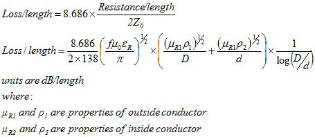
The details of this equation are derived onthis page.
You’d think a fat conductor would always give the lowest insertion loss because it has the most circumferential area (the 1 / d component of the above equation decreases loss for increasing d), but you’d be wrong ! The characteristic impedance of the cable (Z0) throws that log (D / d) function into the denominator, it increases for increasing d.
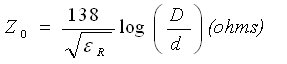
In order to plot loss / length versus characteristic impedance, let’s review the simplified coax impedance calculation. The impedance of coax for a given outer diameter and dielectric is solely a function of the diameter of the inner conductor and the dielectric constant of the filler material:
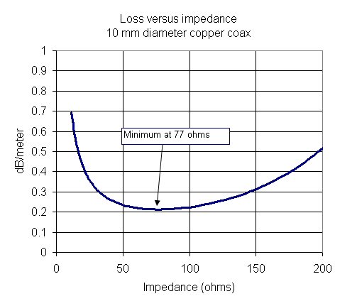
Now we can plot loss / length versus characteristic impedance. It turns out that insertion loss for air dielectric coax has a minimum around 77 ohms, with D / d equal to ~ 3.5. In our example, we chose 10 mm inner diameter of the outer conductor, and calculated loss at 10 GHz. Note air dielectric provides the lowest loss as it eliminates dielectric loss, but it is not always practical. You need at leastsomedielectric to support the center conductor, even if it is just occasional small chunks. Did you ever hear ofheliax air dielectric cable? A spiral of dielectric material is used to pin the center conductor away from the outer conductor.
Peak power handling
Thepeak power handling for air coax is limited by voltage breakdown (as opposed to heating effects which limitaverage power handling). You’d think that you’d want maximum separation between the opposing conductors (inner wire and outer sheaf) to avoid arcing, so you’d make the inner conductor as thin as possible, but you’d be wrong again! The maximum voltage field in a coaxial cable if quite different than between parallel-plane conductors. Here’s the equation for “field enhancement”, which is a measure of how much worse the fields are than in parallel plate:
Beta=(a / r) / [ln(1 a/r)]
Here a is the is the gap between the conductors and r is the radius of the inner conductor. We took this fromGilmour’s book. Once again, characteristic impedance has to be considered because power depends on V2/ Z0.
The way to calculate maximum power handling is to assume a critical electric field that can’t be exceeded to avoid breakdown. We’ll assume 100, 000 volts / meter (actually it can exceed 1, 000, 000 volts per meter, but the wholetopic of voltage breakdowndeserves a lot more attention so we’ll be conservative here for the time being). Next, calculate the field that would be generated across the gap in the coax cable, without regard to the geometry (assume the center and outer conductors are parallel plates). Then apply the field enhancement equation above (which is a number greater than 1). Then the maximum power is equal to Vcritical ^ 2 / (2Z0)). Why the “2” in the denominator? That’s because Vcritical is a peak value, not an RMS value.
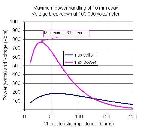
The best peak power handling of air coax occurs at Z0=30 ohms. Please go to our page oncoax power handlingfor more information.
The voltage breakdown of air coax is a function of atmospheric pressure (or altitude), temperature, humidity, and even surface roughness. How do you increase the power handing of air coax? that’s easy, fill it with a dielectric such as PTFE! Typical “solid” dielectric withstanding voltage is much higher that the breakdown voltage of air, by a factor of 10 or more. Foamed dielectrics used in cables don’t provide much of an increase in voltage handling compared to air, but semi-rigid coax (solid PTFE) can handle 10 s of kilowatts, the overall voltage limitation is usually the connectors that are attached to the cables.
New for August 2017 :the peak power handling of air coax may not be at 30 ohms, if you consider another limitation. Suppose you are operating very close to the cut-off of the unwanted (TE) mode. Heck, let’s assume you want to operate exactly at the TE 11 Cut-off. TE 11 cuts off when (D d) * pi / 2 is equal to the operating wavelength. The answer is that at TE 11 cut-off, 44 ohms carries the most power. You can find this fun fact and many more inIntroduction to Microwavesby Gershon J. Wheeler and Irving L. Kosow, dating back to 1963. Our friend Alex did the math for us – check it out inall its gory detail!
The 50 – ohm compromise
For air dielectric coax, the arithmetic mean between (ohms (best power handling) and 77 ohms (lowest loss) is 53 5 ohms, the geometric mean is 48 Ohms. Thus the choice of 50 ohms cam be considered a compromise between power handling capability and signal loss per unit length, for air dielectric.
But wait, there is perhaps a more practical reason for choosing fifty ohms: a coaxial cable with polyethelene (PE) dielectric (ER=2. 25) has minimum loss at 51 2 ohms, with (D / d=3.6) . Thanks to Per!
Why 75 Ohms?
For cheap commercial cables such as those that bring CATV to your home, 75 ohms is the standard. These cables don’t have to carry high power, so the key characteristic that should be considered is low loss. The answer to the “why 75 Ohms? ” question seems obvious. We just saw that 77 ohms gives the lowest loss for air dielectric coax, so 75 ohms might be just an engineering round-off. We know of one text book that will tell you that is why RG cables are 75 ohms … but they are wrong!
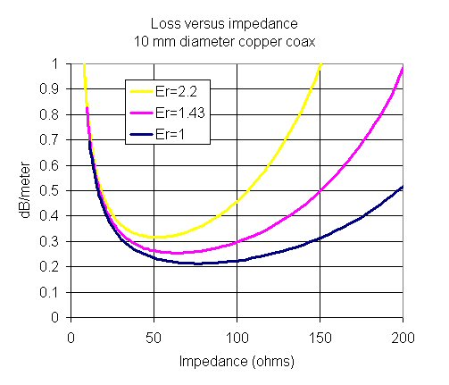
Here’s the problem. Commercial CATV cables are filled with PTFE foam, which has a dielectric constant around 1. 43. Guess what? The loss characteristic is a function of the dielectric constant (~ SQRT (ER)), while impedance is a different function of dielectric constant (~ 1 / [SQRT(ER)]). The opposing contributions of Er muddy the waters quite a bit.
It turns out that the minimum loss impedance for ER=1. 43 is around 64 ohms, as shown in the plot below (purple trace). For the record, for solid PTFE (ER=2.2, yellow line) the minimum loss occurs near 52 ohms. So it’s serendipity that when we use 50 ohm semirigid coax cables with solid PTFE, they give nearly the lowest possible loss for ER=2.2! PTFE was invented byRoy Plunkett in 1938, well after the 50 ohm standard was in place.
So why 75 Ohms? Here’s our guess. Often the center conductor of cheap cables is made of a steel core, with some copper plating. The lower the impedance, the bigger the diameter of the center core. An impedance 75 ohms probably was a compromise between low loss and cable flexibility.
Another microwave myth debunked here at Microwaves 101 .com! Are we not nerds?


GIPHY App Key not set. Please check settings