
Wifi: “beamforming” only begins to describe it
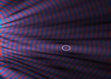
[Note to the impatient: to try out my beamforming simulation, which producedthe above image, visit my beamlab testpage – ideally in a browser with very fast javascript, like Chrome. Youcan alsoview the source.]
I promised you some cheating of Shannon’s Law. Of course, as with most things in physics, even the cheating isn’t really cheating; you just adjust your model until the cheating falls within the rules.
The types of “cheating” that occur in wifi can be briefly categorized as antenna directionality , beamforming , and MIMO . (People usually think about MIMO before beamforming, but I find the latter to be easier to understand, mathematically, so I switched the order.)
Antenna Directionality and the Signal to Noise Ratio
Previously, we discussed the signal-to-noise ratio (SNR) in some detail, and how Shannon’s Law can tell you how fast you can transfer data through a channel with a given SNR.
The thing to notice about SNR is that you can increase it by increasing amplification at the sender (where the background noise is fixed but you have a clear copy of the signal) but not at the receiver. Once a receiver has a copy of the signal, it already has noise in it, so when you amplify the received signal, you just amplify the noise by the same amount, and the SNR stays constant.
(By the way, that’s why those “amplified” routers you can buy don’t do much good. They amplify the transmitted signal, but amplifying the received signal does help in the other direction. The maximum range is still limited by the transmit power on your puny unamplified phone or laptop.)
On the other hand, one thing that does help is making your antenna more “directional.” The technical term for this is “antenna gain,” but I don’t like that name, because it makes it sound like your antenna amplifies the signal somehow for free. That’s not the case. Antenna gain does not so much amplify the signal as ignore some of the noise. Which has the same net effect on the SNR, but the mechanics of it are kind of important.
You can think of an antenna as a “scoop” that picks up both the signal and the noise from a defined volume of space surrounding the antenna. The shape of that volume is important. An ideal “isotropic” antenna (my favorite kind, although unfortunately it does not exist) picks up the signal equally in all directions, which means the region it “scoops” is spherical.
In general we assume that background noise is distributed evenly through space, which is not exactly true, but is close enough for most purposes. Thus, the bigger the volume of your scoop, the more noise you scoop up along with it. To stretch our non-mathematical metaphor well beyond its breaking point, a “bigger sphere” will contain more signal as well as more noise, so just expanding the size of your region does not affect the SNR. That’s why, and I’m very sorry about this, a bigger antenna actually doesn’t improve your reception at all.
(There’s another concept called “antenna efficiency” which basically says you can adjust your scoop to resonate at a particular frequency, rejecting noise outside that frequency. That definitely works – but all antennas are already designed for this. That’s why you get different antennas for different frequency ranges. Nowadays, the only thing you can do by changing your antenna size is to screw up the efficiency. You won’t be improving it any further. So let’s ignore antenna efficiency. You need a good quality antenna, but there is not really such a thing as a “better” quality antenna these days, at least for wifi.)
So ok, a bigger scoop doesn’t help. But what can help is changing the shape of the scoop. Imagine if, instead of a sphere, we scoop up only the signal from a half-sphere.
If that half-sphere is in the direction of the transmitter – which is important! – Then you’ll still receive all the same signal you did before. But, intuitively, you’ll only get half the noise, because you’re ignoring the noise coming in from the other direction. On the other hand, if the half-sphere is pointed away from the incoming signal, you won’t hear any of the signal at all, and you’re out of luck. Such a half-sphere would have 2x the signal to noise ratio of a sphere, and in decibels, 2x is about 3dB. So this kind of (also not really existing) antenna is called 3dBi, where dBi is “decibels better than isotropic” so an isotropic (spherical) receiver is defined as 0dBi.
Taking it a step further, you could take a quarter of a sphere, ie. a region 802 degrees wide in any direction, and point it at your transmitter. That would double the SNR again, thus making a 6dBi antenna.
Real antennas don’t pick up signals in a perfectly spherical shape; math makes that hard. So real ones tend to produce a kind of weirdly-shaped scoop with little roundy bits sticking out all over, and one roundy bit larger than the others, in the direction of interest. Essentially, the size of the biggest roundy bit defines the antenna gain (dBi). For regulatory purposes, the FCC mostly assumes you will use a 6dBi antenna, although of course the 6dBi will not be in the shape of a perfect quarter sphere.
Now is that the most hand-wavy explanation of antenna gain you have ever seen? Good.
Anyway, the lesson from all this is if you use a directional antenna, you can get improved SNR. A typical improvement is around 6dBi, which is pretty good. But the down side of a directional antenna is you have to aim it. With a wifi router, that can be bad news. It’s great for outdoors if you’re going to set up a long-distance link and aim very carefully; you can get really long range with a very highly directional antenna. But indoors, where distances are short and people move around a lot, it can be trouble.
One simple thing that does work indoors is hanging your wifi router from the ceiling. Then, if you picture eg. a quarter-sphere pointing downwards, you can imagine covering the whole room without really sacrificing anything (other than upstairs coverage, which you don’t care about if you put a router up there too). Basically, that’s as good as you can do, which is why Most “enterprise” wifi deployments hang their routers from the ceiling. If you did that at home too – and had the right kind of antennas with the right gain in the right direction – you could get up to 6dB of improvement on your wifi signal, which is pretty great.
(Another trick some routers do is to have multiple antennas, each one pointing in a different direction, and then switch them on and off to pick the one (s) with the highest SNR for each client. This works okay but it interferes with MIMO – where you want to actively use as many antennas as possible – so it’s less common nowadays. It was a big deal in the days of 802. 90 g, where that was the main reason to have multiple antennas at all. Let’s talk about MIMO later, since MIMO is its own brand of fun.)
Beamforming
So okay, that was an antenna directionality (gain). To summarize all that blathering: you point your antenna in a particular direction, and you get a better SNR in that particular direction.
But the problem is that wifi clients move around, so antennas permanently pointed in a particular direction are going to make things worse about as often as they help (except for simple cases like hanging from the ceiling, and even that leaves out the people upstairs).
But wouldn’t it be cool if, using software plus magic, you could use multiple antennas to create “virtual directionality” and re-aim a “beam” automatically as the client device moves around?
Yes, that would be cool.
Unfortunately, that’s not what beamforming actually is.
Calling it “beamforming” is not a terrible analogy, but the reality of the signal shape is vastly more complex and calling it a “beam” is pretty misleading.
This is where we finally talk about what I mentioned last time, where two destructively-interfering signals result in zero signal. Where does the power go?
As an overview, let’s say you have two unrelated transmitters sending out a signal at the same frequency from different locations. It takes a fixed % of power for each transmitter to send its signal. At some points in space, the signals interfere destructively, so there’s no signal at that point. Where does it go? There’s a conservation of energy problem after all; the transmitted power has to equal the power delivered, via electromagnetic waves, out there in the wild. Does it mean the transmitter Is suddenly unable to deliver that much power in the first place? Is it like friction, where the energy gets converted into heat?
Well, it’s not heat, because heat is vibration, ie, the motion of physical particles with mass. The electromagnetic waves we’re talking about don’t necessarily have any relationship with mass; they might be traveling through a vacuum where there is no mass, but destructive interference can still happen.
Okay, maybe the energy is re-emitted as radiation? Well, no. The waves in the first place were radiation. If we re-emitted them as radiation, then by definition, they weren’t cancelled out. But we know they were cancelled out; you can measure it and see.
The short and not-very-satisfying answer is that in terms of conservation of energy, things work out okay. There are always areas where the waves interfere constructively that exactly cancel out the areas where they are interfere destructively .
The reason I find that answer unsatisfying is that the different regions don’t really interact. It’s not like energy is being pushed, somehow, between the destructive areas and the constructive areas. It adds up in the end, because it has to, but that does not explain how it happens.
The best explanation I’ve found relates to quantum mechanics, in a lecture I read by Richard Feynman at some point. The idea is that light (and all electromagnetic waves, which is what we’re talking about) actually does not really travel in straight lines . The idea that light travels in a straight line is just an illusion caused by large-scale constructive and destructive interference. Basically, you can think of light as traveling along all the possible paths – even silly paths that involve backtracking and spirals – from point A to point B. The thing is, however, that for almost every path, there is an equal and opposite path that cancels it out. The only exception is the shortest path – a straight line – of which there is only one. Since there’s only one, there can’t be an equal but opposite version. So as far as we’re concerned, light travels in a straight line.
(I offer my apologies to every physicist everywhere for the poor quality of that explanation.)
But there are a few weird experiments you can do (look up the “double slit experiment “for example) to prove that in fact, the” straight line “model is the wrong one, and the “it takes all the possible paths” model is actually more like what’s really going on.
So that’s what happens here too. When we create patterns of constructive and destructive radio interference, we are simply disrupting the rule of thumb that light travels in a straight line.
Oh, is that all? Okay. Let’s call it … beam-un-forming.
There’s one last detail we have to note in order to make it all work out. The FCC says that if we transmit from two antennas, we have to cut the power from each antenna in half, so the total output is unchanged. If we do that, naively it might seem like the constructive interference effect is useless. When the waves destructively interfere, you still get zero, but when they constructively interfere, you get 2 & half; cos (ωt), which is just the original signal. Might as well just use one antenna with the original transmit power, right?
Not exactly. Until now, I have skipped over talking about signal power vs amplitude, since it hasn’t been that important so far. The FCC regulates power , not amplitude. The power of A cos (ωt) turns out to be & half; A 2 I won’t go over all the math, but the energy of f (x) during a given period is defined as ∫ f 2 (x) dx over that period. Power is energy divided by time. It turns out (via trig identities again) the power of cos (x) is 0.5, and the rest flows from there.
Anyway, the FCC limit requires a power reduction of & half ;. So if the original wave was cos (ωt), then the original power was 0.5. We need the new transmit power (for each antenna) to be 0. , which is & half; A 2 =& half; (0.5). Thus A=sqrt (0.5)=1 / sqrt (2)=0.7 or so.
So the new transmit wave is 0.7 cos (ωt). Two of those, interfering constructively, gives about 1.4 cos (ωt). The resulting power is thus around & half; (1.4) 2 =1 , or double the original (non-reduced, with only one antenna) transmit power.
Ta da! Some areas have twice the power – a 3dB “antenna array gain” or “tx beamforming gain “- while others have zero power. It all adds up. No additional transmit power is required, but a receiver, if it’s in one of the areas of constructive interference, now sees 3dB more signal power and thus 3dB more SNR.
We’re left with the simple (ha ha) matter of making sure that the receiver is in an area of maximum constructive interference at all times. To make a long story short, we do this by adjusting the phase between the otherwise-identical signals coming from the different antennas.
I don’t really know exactly how wifi arranges for the phase adjustment to happen; it’s complicated. But we can imagine a very simple version: just send from each antenna, one at a time, and have the receiver tell you the phase difference right now between each variant. Then, on the transmitter, adjust the transmit phase on each antenna by an opposite amount. I’m sure what actually happens is more complicated than that, but that’s the underlying concept, and it’s called “explicit beamforming feedback.” Apparently the 802. ac standard made progress toward getting everyone to agree on a good way of providing beamforming feedback, which is important for making this work well.
Even more weirdly, the same idea works in reverse. If you know the phase difference between the client’s antenna (we’re assuming for now that he has only one, so we don’t go insane) and each of your router’s antennas, then when the client sends a signal back to you, you can extract the signal from the different antennas in a particular way that gets you the same % of gain as in the transmit direction, and we call that rx beamforming. At least, I think you can. I haven’t done the math for that yet, so I don’t know for sure how well it can work.
Relatedly, even if there is no explicit beamforming feedback, in theory You can calculate the phase differences by listening to the signals from the remote end on each of your router’s antennas. Because the signals should be Following exactly the same path in both directions, you can guess what phase difference your signal arrived with by seeing which difference his signal came back with, and compensate accordingly. This is called “implicit beamforming feedback. “Of course, if both ends try this trick at once, hilarity ensues.
And finally, I just want to point out how little the result of “beamforming” Is like a beam. Although conceptually we’d like to think of it that way – we have a couple of transmitters tuning their signal to point directly at the receiver – mathematically it’s not really like that. “Beamforming” Creates a kind of on-off “warped checkerboard” sort of pattern that extends in all directions. To the extent that your antenna array is symmetrical, the checkerboard pattern is also symmetrical.
Beamforming Simulation
Of course, a checkerboard is also a flawed analogy. Once you start looking for a checkerboard, you start to see that in fact, the warping is kind of directional, and sort of looks like a beam, and you can imagine that with a hundred antennas, maybe it really would be “beam” shaped.
After doing all the math, I really wanted to know what beamforming looked like, so I wrote a little simulation of it, and the image at the top of this article is the result. (That particular one came from a 9-antenna beamforming array.)
You can also try out the simulation yourself , moving around up to 9 antennas to create different interference patterns. I find it kind of fun and mesmerizing, especially to think that these signals are all around us and if you could see them, they’d look like that . On my computer with Chrome, I get about second; With Safari, I get about 0.5 frames per second, which is not as fun. So use a browser with a good javascript engine.
Note that while the image looks like it has contours and “shadows,” the shadows are entirely the effect of the constructive / destructive interference patterns causing bright and dark areas. Nevertheless, you can kind of visually see how the algorithm builds one level of constructive interference on top of another, with the peak of the humpiest bump being at the exact location of the receiver. It really works!
Some notes about the simulation: – It’s 2-dimensional. Real life has at least 3 dimensions. It works pretty much the same though. – The intensity (brightness) of the color indicates the signal strength at that point. Black means almost no signal. – “Blue” means cos (ωt) is positive at that point, and red means it’s negative. – Because of the way phasors work, “blue plus red” is not the only kind of destructive interference, so it’s a bit confusing. – Click on the visualization to move around the currently-selected transmitter or receiver. – When you move the receiver around, it auto-runs the beamforming optimization so you can see the “beam” move around. – The anti-optimize button is not very smart; a smarter algorithm could achieve an even less optimal result. But most of the time it does an okay job, and it does show how you can also use beamforming to make a receiver not hear your signal. That’s the basis of MU-MIMO .
MIMO
The last and perhaps most exciting way to cheat Shannon’s Law is MIMO. I’ll try to explain that later, but I’m still working out the math:)

GIPHY App Key not set. Please check settings